Soldering Usb Connection Wiring Diagram. Web next, heat the connection with the soldering iron while holding the solder wire against it. At this time, only a little tin is left on the surface of the solder joint.
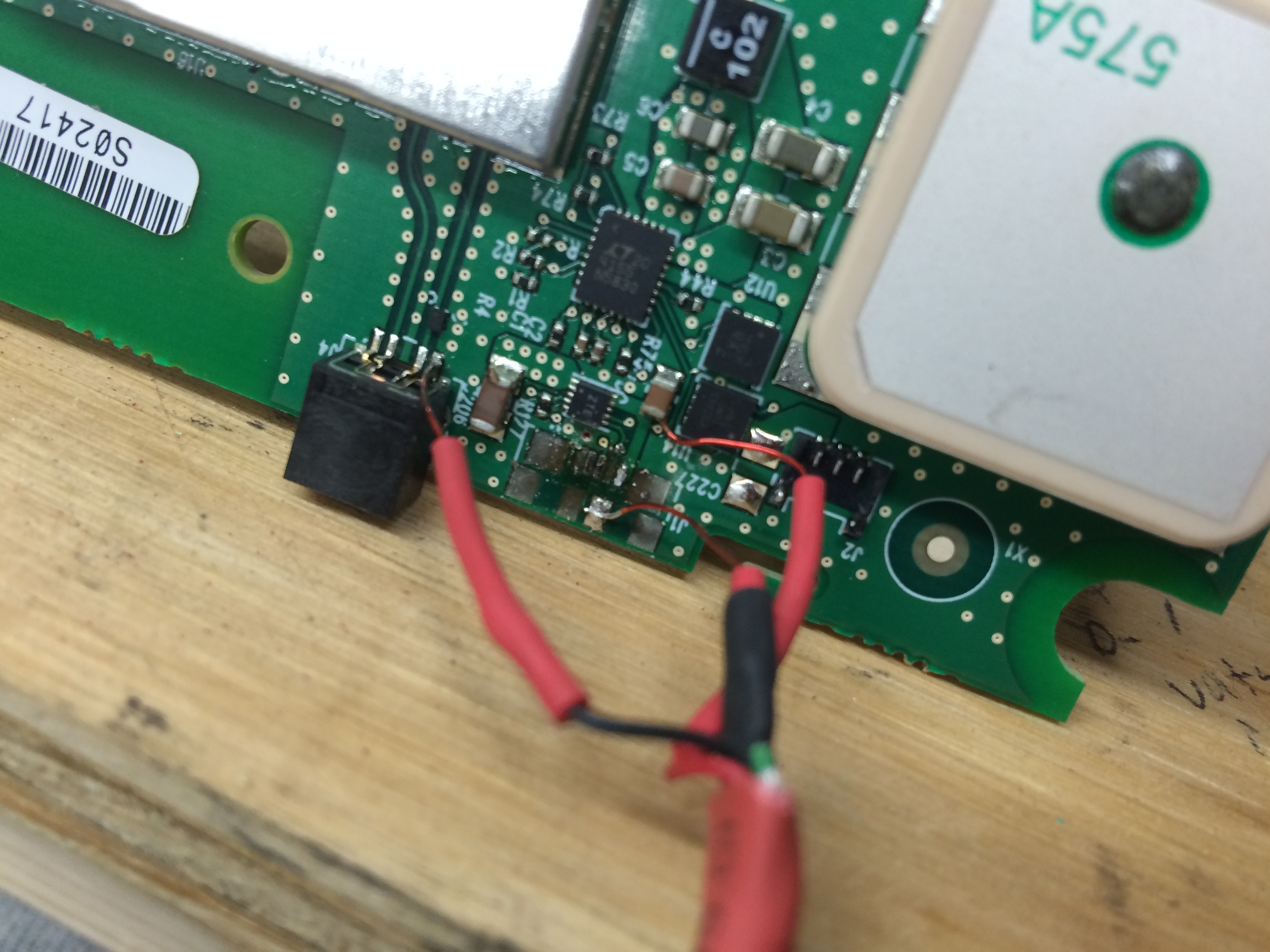
(not) Fixing The Broken Micro USB Port on a First Generation Stratus from bearhawkblue.com
The heat should draw the solder into the joint, creating a solid. Web cut the sleeving at the end of the usb3.0 cable and it will give you a perfect length after you put on the usb3.0 external headers. In the case of usb soldering irons, the circuit diagram will provide you with.
My Soldering And Drawing Skills Are Not The Very Best But With The Help Of.
At this time, only a little tin is left on the surface of the solder joint. Then, using the wiring diagram provided with the usb to serial. Now as far as i know.
This Process Makes It Fairly Straightforward And Reduces The Number.
Web in this video i'm showing you my soldering process for the most common usb connectors used for these types of cables. Web there are four conductors in a usb 1.1/2.0 cable to wire up in the cable connectors: Also i'll be adding the metal housings.
Place The Tip Of The Soldering Iron Against The Solder Pad.
Web in this video i tried to explain the connection diagram of a micro usb connector. Web usb c cable wiring diagram. Melt just enough solder onto the solder pad so that the contact leads hold firmly in.
Web Generally Speaking, A Circuit Diagram Is A Visual Representation Of How A Specific Device Is Wired.
Solder the wires of the usb cables between them. Web to begin, locate the serial port on the usb device. In the case of usb soldering irons, the circuit diagram will provide you with.
Web The Purpose Is To Prevent Excessive Tin From Causing False Soldering.
The heat should draw the solder into the joint, creating a solid. Web the problem is that when i disassembled the item i saw that the cable is soldered to 5 points to the board using 5 cables that come out of it. You have to solder the wire corresponding to pin 4 of the cable 1 with the wire corresponding to pin.